Introduction
Operators are exposed to fume and gases when welding, and
exposures vary depending upon the process and specific working
conditions. Fabricators are under continual pressure to reduce
worker exposure to potentially harmful substances in the
workplace, including welding fume. This article will address the
following:
How welding fume is
generated
Coordinating
factors that affect fume generation and exposure to fume such as
welding design, process, equipment, consumables, gases, work management and ventilation
Highlights of fume
extraction technology
The current
regulatory climate with regard to welding fume
Current
published exposure limits for typical components of fume
What Is Welding Fume?
Although many people think of gases and vapors from gasoline or
other chemicals as "fume," technically, fume is comprised of
very small, solid particles. Since Arc welding usually produces
only small concentrations of gases, exposure to gases is seldom
a concern except in confined areas. Therefore, the issue of
secondary gas production will not be specifically discussed
here.
Arc welding creates fume as some of the metal boils from the
tip of the electrode and from the surface of molten droplets as
they cross the arc. This metal vapor combines with oxygen in the
air and solidifies to form tiny fume particles. These particles
are visible because of their quantity, but each particle is only
between 0.2 and 1.0 micron in size. Since fume primarily comes
from the electrode, it consists of oxides of its metals, alloys
and flux compounds. In steel welding, therefore, fume is
primarily iron oxide and oxides of alloys such as manganese and
chromium. With plated or coated metals, some of the fume comes
from the weld pool as well. This adds oxides of metals from the
base material into the fume such as zinc oxide from welding
galvanized steels.
A Total Systems Approach
There are many ways to reduce exposure to welding fume. Each
solution addresses part of the welding system. Each solution,
however, has its advantages and disadvantages and should be
considered in the context of the total system. Likewise, a
solution cannot work without proper implementation. The most
successful solutions rely on a coordinated effort between
managers, engineers, welding supervisors, vendors and especially
welders themselves.
Although "fume extraction" may be the first solution that
comes to mind, other options should be considered as well.
Approaches to controlling welding fume actually fall into two
broad categories:
Reducing fume
generation
Limiting operator
exposure to fume
Reducing Fume Generation
Welding Design Considerations
 Limiting the generation of welding fume begins at the design
stage. All other things being equal, a properly sized weld will
result in the lowest amount of welding fume for a given process
and set of procedures. Overwelding, on the other hand,
unnecessarily increases welding fume. As the amount of weld
metal increases, the amount of fume also increases. The welding
engineer should be aware of the role that weld size plays in the
creation of fume.
Limiting the generation of welding fume begins at the design
stage. All other things being equal, a properly sized weld will
result in the lowest amount of welding fume for a given process
and set of procedures. Overwelding, on the other hand,
unnecessarily increases welding fume. As the amount of weld
metal increases, the amount of fume also increases. The welding
engineer should be aware of the role that weld size plays in the
creation of fume.
Welding Process Selection
Significant reductions in fume creation can come with a change
in the welding process. Therefore, fabricators and welding
supervisors should be aware of the impact process selection will
have on fume generation. They must also remember, however, that
each process offers specific advantages and disadvantages for a
given application and a given situation.
Submerged Arc Welding (SAW) contains the majority of the fume
(and the arc) under a bed of flux, making it an excellent choice
when reducing fume generation is a primary concern. This process
has certain limitations, however. SAW requires flat or
horizontal positioning, slag cleaning, maintenance of the
granular flux, and is most commonly used for mechanized welding
of relatively thick steel plate.
Gas Tungsten Arc Welding (GTAW) also produces very little
fume, since the filler metal does not carry the welding current,
and the arc is very stable. However, manual GTAW is a low
deposition rate process requiring highly skilled operators. As
such, it is often the process of choice for precision welding or
certain special applications. Using GTAW to weld heavy plate
would not be practical.
Flux Cored Arc Welding (FCAW) processes are usually
considered the largest fume producers due to typically high
deposition rates. However, many applications are best served by
FCAW precisely because of its high deposition rates, especially
in out-of-position applications. Fume generation rates vary
widely, depending upon the electrode type, grade, and design.
The design of the electrode can have a major impact on the
amount of fume that will be generated. Several manufacturers
offer reduced fume flux cored electrodes. Research indicates
that some metal cored electrodes used with a pulsed current
power source can yield low fume generation rates as well.
Gas Metal Arc Welding (GMAW) is a practical option for many
applications, from thin sheet metal to heavy plate. Fume
generation in GMAW depends upon procedures, droplet transfer,
shielding gas, and the grade of electrode used. ER70S-6, for
instance, has higher levels of manganese than ER70S-3. Since
manganese levels are often a key factor in determining
regulatory compliance, this can be a significant issue.
Shielding Gas
The shielding gas also affects arc physics and fume
generation. The energy levels required to dissociate and ionize
the various gases relates to the excess energy available to boil
metal from the electrode and molten droplet. In practice, using
100% CO2 will require a procedure increase of 1-2 volts compared
to Argon blends. This adds energy to the arc, boiling off more
metal and creating more fume. Although some active gas is needed
in GMAW and FCAW of steels, higher percentages of argon in
blended gases tend to reduce fume generation. These blends tend
to be more expensive than 100% CO2, especially in Europe and
Asia.
Waveform Control Technology?/strong>
Another way to reduce fume generation is to use one of the
various waveform controlling power sources. With pulsed GMAW,
for example, less fume is typically produced than with a
conventional constant voltage power source. In this mode, the
arc is controlled by pulsing the current from a background level
to a peak level at a specified frequency. This reduces the total
arc energy and decreases the amount of metal that is vaporized,
which leads to reduced fume generation.
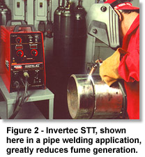 Invertec STT II - pipe welding, low fume applicationLincoln
Electric's new STT?inverter is another waveform controlled
power source that has led to the creation a new transfer mode:
Surface Tension Transfer?(STT) welding. In conventional
short-circuit transfer, the current rises to high levels
immediately before the droplet detaches from the electrode
causing some of the electrode to vaporize. This causes violent
droplet detachment and creation of spatter and fume. The STT
power source is able to control the current during droplet
transfer. When the droplet is about to detach, the current level
decreases, and the droplet is pulled into the puddle by surface
tension forces resulting is reduced spatter. After detachment,
current is then controlled to prevent overheating the tip of the
electrode. This control significantly reduces droplet
temperatures and increases arc stability. Spatter can be
decreased by 90% and fume generation by 50%, compared to
conventional short-arc transfer. STT, however, is limited to
applications appropriate for short-circuit transfer.
Invertec STT II - pipe welding, low fume applicationLincoln
Electric's new STT?inverter is another waveform controlled
power source that has led to the creation a new transfer mode:
Surface Tension Transfer?(STT) welding. In conventional
short-circuit transfer, the current rises to high levels
immediately before the droplet detaches from the electrode
causing some of the electrode to vaporize. This causes violent
droplet detachment and creation of spatter and fume. The STT
power source is able to control the current during droplet
transfer. When the droplet is about to detach, the current level
decreases, and the droplet is pulled into the puddle by surface
tension forces resulting is reduced spatter. After detachment,
current is then controlled to prevent overheating the tip of the
electrode. This control significantly reduces droplet
temperatures and increases arc stability. Spatter can be
decreased by 90% and fume generation by 50%, compared to
conventional short-arc transfer. STT, however, is limited to
applications appropriate for short-circuit transfer.
Limiting Operator Exposure to Fume
The second broad category of controlling welding fume covers
methods of limiting personnel exposure to the fume. Management
will be responsible for initiating the decisions in this
category, while employees at various levels of the organization
will need cooperate to ensure their success.
Job Sharing
The most direct approach to limiting personnel exposure is
simply to limit the amount of time an operator spends welding.
This can often be accomplished via job sharing. For example, an
operator could spend half a day welding an SAW application, and
the remainder of the day welding an FCAW application. Or, the
second half of the day might be spent driving a forklift. It is
not a cost-free method; after all, twice as many individuals
must be trained and qualified as welding operators for any given
application. However, it can yield dividends in terms of higher
productivity, greater job satisfaction resulting from mastering
a variety of tasks, and a more versatile, cross-trained
workforce. This simple approach deserves thoughtful
consideration by management.
Automated Welding Systems
Robotics and other automated welding systems provide another
route to limiting employee exposure to welding fume. Automation
can be a viable alternative if the initial capital expense can
be justified by higher productivity and improved quality.
However, automated welding cells commonly operate at high duty
cycles, and employee exposure to fume must still be evaluated.
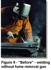
Fume Extraction Technology
The one method of fume control effective for almost any welding
process is ventilation. Since the operator's breathing zone is
the critical area, localized ventilation, usually called "fume
extraction," is the
 preferred method. Fume extraction technology
falls into two categories: low vacuum/high volume, or high
vacuum/low volume.
preferred method. Fume extraction technology
falls into two categories: low vacuum/high volume, or high
vacuum/low volume.
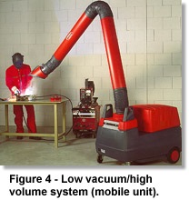
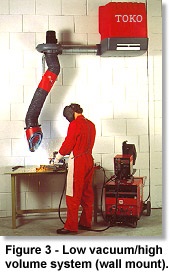
Low vacuum/high volume system (mobile unit) Low Vacuum/High
Volume
Regular building ventilation systems are low vacuum, high volume
systems, sometimes called "low static, high flow." When industry
needed better ventilation solutions, many companies modified low
vacuum systems for localized ventilation. Hoses 6 to 9 inches
(160 - 200 mm) in diameter were added for flexibility and
eventually structures were designed to support the hoses and
make it easier to position them. Manufacturers began to make
these arms with different designs and features, and they are
still used in many industries, including the welding industry.
The articulated arms generally move between 600 and 900 cubic
feet (900 - 1500 m3/hr) per minute (CFM) of air, but use low
vacuum levels (3 to 5 inches water gauge [750 -
 1250 Pa]) to
minimize power requirements. Water gauge (WG) is a measure of
negative pressure: higher numbers mean more negative pressure
(more "suction"). With this volume of airflow, the end of the
arm can be generally 10 to 15 inches (250 - 375 mm) away from
the arc and still capture the fume. Articulated fume extraction
arms are produced by a wide range of manufacturers, using 6 inch
or 8 inch hose, or hose and tubing combinations. Lengths are
typically 7, 10, or 13 feet (2, 3 or 4 m), with boom extensions
available. The arms may be wall mounted, attached to mobile
units, or incorporated into a centralized system.
1250 Pa]) to
minimize power requirements. Water gauge (WG) is a measure of
negative pressure: higher numbers mean more negative pressure
(more "suction"). With this volume of airflow, the end of the
arm can be generally 10 to 15 inches (250 - 375 mm) away from
the arc and still capture the fume. Articulated fume extraction
arms are produced by a wide range of manufacturers, using 6 inch
or 8 inch hose, or hose and tubing combinations. Lengths are
typically 7, 10, or 13 feet (2, 3 or 4 m), with boom extensions
available. The arms may be wall mounted, attached to mobile
units, or incorporated into a centralized system.
For greater capture distances, a larger volume of air is
required to achieve the necessary "capture velocity" and capture
the fume. In practice, however, longer capture distances may
mean that breathing zone exposure is compromised. Overhead
hoods, for example, capture most of the fume, but only after it
has passed through the breathing zone of the operator.
Cross draft ventilation is a variation of overhead hood
technology. These systems use a plenum with openings to the side
of the work space, rather than above it. Therefore, the fume
moves sideways, away from the operator's breathing zone. These
systems can be effective for small booths when small parts are
being welded. The CFM required for effectiveness varies
depending upon the installation design, but frequently can be
1,000 CFM or higher.
There are, however, certain disadvantages associated with the
low vacuum systems. For example, in systems incorporating
articulated fume extraction arms, the operator must stop to
reposition the arm over each weld area, which diminishes
productivity. These arms also have limited reach, commonly 10 to
13 feet. The high volume of air flow requires large hoses, and
ductwork ranging from 8 to 36 inches in diameter or more,
depending upon the installation. Exhausting air outside often
requires make-up air systems and make-up air heaters. Filtration
systems are large due to the high air volume being processed.
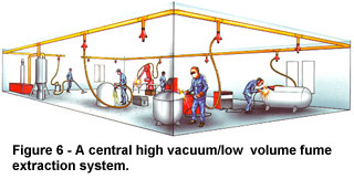
High Vacuum/Low Volume
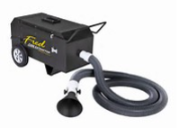 High vacuum/low volume fume extraction systems are much more
specific to point-source applications such as welding. Their
chief advantage: they remove the fume directly at the source,
within inches of the arc. This means that fume is captured
before it can reach the operator's breathing zone or disperse
into the room. Because of the close proximity to the source,
fume extraction can be achieved with lower airflow rates,
typically 80 to 100 CFM for suction nozzles, depending upon the
design, and 35 to 60 CFM for integrated fume extraction guns.
The vacuum level is high (40 to 70 inches WG), permitting the
use of hose featuring longer lengths (10 to 25 feet) and smaller
diameters (1.25 to 1.75 inches). High vacuum equipment ranges
from small, portable units to mobile three-phase systems, to
large, centralized systems.
High vacuum/low volume fume extraction systems are much more
specific to point-source applications such as welding. Their
chief advantage: they remove the fume directly at the source,
within inches of the arc. This means that fume is captured
before it can reach the operator's breathing zone or disperse
into the room. Because of the close proximity to the source,
fume extraction can be achieved with lower airflow rates,
typically 80 to 100 CFM for suction nozzles, depending upon the
design, and 35 to 60 CFM for integrated fume extraction guns.
The vacuum level is high (40 to 70 inches WG), permitting the
use of hose featuring longer lengths (10 to 25 feet) and smaller
diameters (1.25 to 1.75 inches). High vacuum equipment ranges
from small, portable units to mobile three-phase systems, to
large, centralized systems.
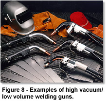
There are two methods of high vacuum extraction: welding guns
with built-in extraction, or separate suction nozzles of various
designs. (Photo.) Suction nozzles are positioned near the weld,
typically with magnets, and commonly use capture distances of
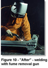
less than four inches. Fume extraction guns use fume capture
nozzles built into the gun tube and handle. Therefore, no
repositioning is required, since the suction automatically
follows the arc.
 High vacuum extraction, like other solutions, has its
limitations. Although manufacturers have greatly improved
designs, fume extraction guns are larger than regular welding
guns. Furthermore, fume guns do not control residual fume and
smoke, since the gun is moved away immediately after welding is
completed. Finally, unless they are set in weld fixtures, high
vacuum suction nozzles also require repositioning.
High vacuum extraction, like other solutions, has its
limitations. Although manufacturers have greatly improved
designs, fume extraction guns are larger than regular welding
guns. Furthermore, fume guns do not control residual fume and
smoke, since the gun is moved away immediately after welding is
completed. Finally, unless they are set in weld fixtures, high
vacuum suction nozzles also require repositioning.
Nevertheless, high vacuum/low volume methods of fume
extraction offer significant advantages to welding fabricators.
Of chief importance is the removal of fume right at its source,
before it can reach the operator's breathing zone. Since fume
guns eliminate the repositioning required by articulated arms or
suction nozzles, productivity is not directly reduced.
Many other advantages come from reducing the total amount of
airflow required. A lower volume of air means smaller ductwork,
smaller hoses, much smaller filter systems, and less strain on
make-up air systems if the air is exhausted outside. This
translates into lower material, installation and maintenance
costs. A typical low vacuum system for twenty stations, for
instance, might require an airflow rate of 12,000 CFM, whereas a
high vacuum system serving the same facility could require an
airflow rate as low as 1,200 CFM.
After fume is removed from the source, it is either exhausted
directly to the atmosphere or is passed through an electrostatic
or cartridge filter. Because electrostatic filters lose
efficiency if they are not
 frequently washed, the welding
industry primarily uses more easily maintained cartridge
filters. Most cartridge filters have a high efficiency level,
usually 98% or higher. Although cartridges classified as "HEPA"
have extremely high efficiency when new, they are expensive and
have shorter life. HEPA filters are normally not necessary in
fume extraction equipment, since capture efficiency has a much
greater impact on breathing zone exposure than filtration
efficiency.
frequently washed, the welding
industry primarily uses more easily maintained cartridge
filters. Most cartridge filters have a high efficiency level,
usually 98% or higher. Although cartridges classified as "HEPA"
have extremely high efficiency when new, they are expensive and
have shorter life. HEPA filters are normally not necessary in
fume extraction equipment, since capture efficiency has a much
greater impact on breathing zone exposure than filtration
efficiency.
Regulatory Bodies
Two major types of organizations study and regulate exposure to
welding fume and other particulates in the workplace: industrial
health organizations, and government regulatory agencies. In the
, two major industrial health organizations are the American
Conference of Governmental and Industrial Hygienists (ACGIH) and
the National Institute of Occupational Safety and Health
(NIOSH). They set exposure limits for a variety of materials,
including those found in welding fume. The ACGIH calls their
limit the Threshold Limit Value (TLV). The TLV is influential in
industry and is a standard followed by most insurance companies.
As important as the TLV is, however, it is not enforceable by
law. The Occupational Safety and Health Administration (OSHA) is
the only organization that can establish legally enforceable
limits for exposure to chemicals in the workplace. At both state
and federal levels, OSHA's mandatory Permissible Exposure Limits
(PEL) place tough demands on the welding industry.
Exposure Limits
The limits for fume exposure set by OSHA and others are measured
in milligrams of particulate per cubic meter of air (mg/m3). The
total amount of fume produced is not limited, but rather the
concentration of fume is limited. During facility testing, a
sampling device is placed in the breathing zone of the operator
(e.g., the welding hood, not on the lapel). At the end of the
operator's shift, a number is calculated that reflects an 8-hour
Time Weighted Average (TWA) of the fume concentration in the
operator's breathing zone, in mg/m3.
Since this method focuses on breathing zone exposure, the
results are highly unpredictable, even when the process,
procedure and other influences are consistent. Therefore, to
ensure compliance with exposure limits, companies should test
their own operators while they are welding in everyday
applications to obtain an accurate concentration value. The
results can then be compared to benchmarks such as the TLV or
PEL. If the number is higher than the standard, then that
company is out of compliance.
Listed in Table 1 are the current welding fume exposure
limits as specified by OSHA and ACGIH. Note that the table does
not contain a PEL for total welding fume. The PEL of 5 mg/m3
established in 1989 was challenged in a lawsuit, and is no
longer enforced.
|
Table 1. Exposure Guidelines for Materials Sometimes
Found in Welding Fume |
| ˇˇ |
ACGIH(1)
TLV (mg/m3) |
OSHA(2)
PEL (mg/m3) |
| Welding Fume |
5.0 |
ˇˇ |
| Iron Oxide, as Fe |
5.0 |
10.0 |
| Manganese (all forms) |
0.2 |
1.0(3) 5.0 (c) |
| Chromium III compounds |
0.5 |
0.5 |
| Chromium VI compounds, sol |
0.05 |
0.05 (c) |
| Chromium VI compounds, insol |
0.01 |
0.5 (c) NIC.0005 - .005 (both forms) |
| Nickel, insol compounds, as N |
(1.0) 0.5 NIC |
1.0 |
| Aluminum, Welding Fumes, as Al |
5.0 |
ˇˇ |
| Zinc Oxide, fume |
5.0 10.0 (c) |
5.0 |
| Barium compounds, sol, as Ba |
0.5 |
0.5 |
| Beryllium & compounds, as Be |
0.002 .01(c) |
0.002 .005(c) |
| Cadmium Oxide, as Cd |
0.002 |
0.005 |
| Cobalt oxide, as Co |
0.02 |
0.1 |
| Copper fume, as Cu |
0.2 |
0.1 |
| Flourides, as F |
2.5 |
2.5 |
| Magnesium oxide fume |
10.0 |
15.0 total particulate |
| Molybdenum, insol compounds, as Mo |
10.0 |
15.0 total particulate |
| Tin oxide |
2.0 |
2.0 |
| Vanadium pentoxide, as V2O5 |
0.05 |
0.1(c) |
(1) Threshold Limit Value set by ACGIH (American Conference of
Governmental Industrial Hygenists) based upon 8 hour TWA (Time
Weighted Average), as of 9/98.
(2) OSHA Permissable Exposure Limit based upon 8 hour TWA, as of
9/98.
(3) Short Term Exposure Limit (STEL) for Manganese, based on a
15 minute TWA, is 3 mg/m3
(c) Maximum Exposure Concentration: not to be exceeded at any
time (not a TWA).
NIC - Notice of intended changes
Manganese and chromium are two examples of materials which have
strict time exposure limits as well. When limits are measured on
an 8-hour TWA, an operator may be exposed to high concentrations
in the morning, but the facility may still be in compliance if
concentrations are lower in the afternoon. The limits for
certain forms of chromium are "ceilings," meaning that any
overexposure during the day will cause the facility to fail
compliance.
 Since the regulatory climate regarding welding fume
depends greatly upon the specific state, local regulators should
always be contacted for relevant information. Companies should
check the Material Safety Data Sheet (MSDS) for the welding
electrode they use. The MSDS report will show not only the
composition of the electrode, but also the components of welding
fume that can be created by the welding process. The report also
shows the TLV and PEL for each item, and gives valuable
information concerning health risks and other reference data.
The only way to get a clear picture of where a company stands,
however, is testing operators while they are welding in the
company's actual facilities.
Since the regulatory climate regarding welding fume
depends greatly upon the specific state, local regulators should
always be contacted for relevant information. Companies should
check the Material Safety Data Sheet (MSDS) for the welding
electrode they use. The MSDS report will show not only the
composition of the electrode, but also the components of welding
fume that can be created by the welding process. The report also
shows the TLV and PEL for each item, and gives valuable
information concerning health risks and other reference data.
The only way to get a clear picture of where a company stands,
however, is testing operators while they are welding in the
company's actual facilities.
Conclusion
While exposure to fume can be an issue in any welding
application, no one solution is the best for all of them. Each
solution only addresses part of the welding system and has its
advantages and disadvantages. The best solution will be found
when managers, engineers, welding supervisors, vendors and
welders work together to meet the needs of the company with a
total systems approach.